
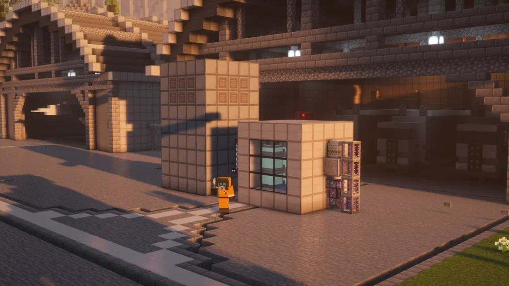
The Industrial Turbine is a Mekanism multiblock that turns Steam into power, and it’s the only way to get energy out of a Fission Reactor or a Thermoelectric Boiler. It’s built as a hollow box of  Turbine Casing with a column of rotors up the middle, anything from 5x5x5 up to 17x17x18. It’s the steam turbine you’ll be looking for in Mekanism.
A small 5x5x9 turbine will already make about 1.5 million FE/t (3.77 million J/t) when it’s given enough Steam, whereas the largest one reaches about 53 million FE/t, built with 10 rotors rather than the full 14. It doesn’t make any Steam itself, so you’ll always be building it alongside a reactor or a boiler.
How to Build It
There are nine different parts in a turbine, and most of them are made from  Steel Ingots with one other ingredient in the middle. The Turbine Casing is the one you’ll need the most of, as it makes up the floor and most of the walls.
| Part | Recipe | Where It Goes |
|---|---|---|
| Turbine Casing | 4 Steel Ingot around an Osmium Ingot (makes 4) | Every edge and corner, and any wall block |
| Turbine Valve | 4 Turbine Casing around an Advanced Control Circuit (makes 2) | Any wall face, for Steam in and power out |
| Turbine Vent | 4 Turbine Casing around Iron Bars (makes 2) | Walls and roof, level with the Rotational Complex or higher |
| Turbine Rotor | 6 Steel Ingot and 3 Infused Alloy | The center column, starting on the floor |
| Turbine Blade | 4 Steel Ingot around an Infused Alloy | Right-clicked onto a rotor, 2 on each |
| Rotational Complex | 4 Steel Ingot, 3 Infused Alloy, 2 Advanced Control Circuit | On top of the highest rotor |
| Pressure Disperser | 4 Steel Ingot, 4 Iron Bars, 1 Infused Alloy | Fills the layer around the Rotational Complex |
| Electromagnetic Coil | 4 Steel Ingot, 4 Gold Ingot, 1 Energy Tablet | Directly above the Rotational Complex |
| Saturating Condenser | 4 Steel Ingot, 4 Tin Ingot, 1 Bucket | Anywhere above the Pressure Disperser layer |
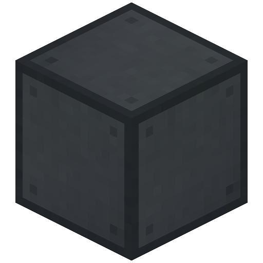
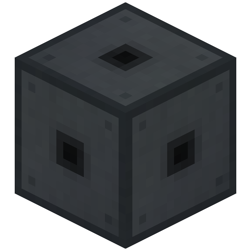
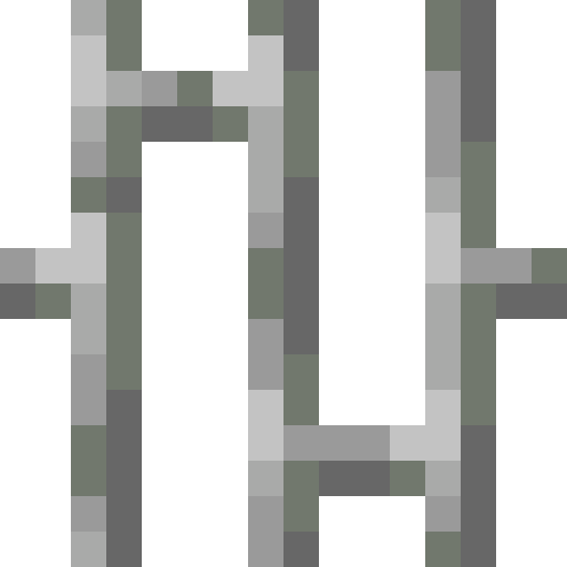
 Structural Glass can be swapped in for casing on any wall face if you’d like to see inside, and so can
 Reactor Glass. The two viewers below have the recipes for the turbine’s own parts, and the
 Pressure Disperser is shared with the Thermoelectric Boiler.


 4

 2
 2

The  Turbine Valve and the
 Turbine Vent are both crafted from casing, so it’s worth making a lot more casing than the build needs. Both recipes give two at a time, which helps with the vents as you’ll be using plenty of them.




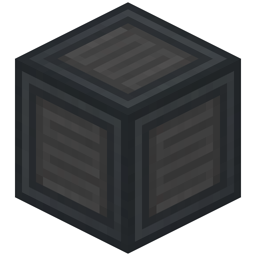
The inner parts are where the Infused Alloy and Advanced Control Circuits go. A  Rotational Complex is only ever needed once, whereas the number of rotors, blades and coils depends on how tall you’re building.
A first turbine, layer by layer
The 5x5x9 turbine is a good one to start with, as it holds the most rotors that a 5 wide base allows. It has 5 rotors with 10 blades, and the table goes through it from the floor up.
| Layer | Outer Ring | Inside |
|---|---|---|
| 1 (floor) | Solid 5×5 of Turbine Casing | None |
| 2 to 6 | Turbine Casing, with the Turbine Valves anywhere but the corners | Turbine Rotor in the center, air around it |
| 7 | Turbine Casing corners, 12 Turbine Vents between them | Rotational Complex in the center, 8 Pressure Dispersers around it |
| 8 | Turbine Casing corners, 12 Turbine Vents between them | Electromagnetic Coil in the center, 2 more touching it, 6 Saturating Condensers |
| 9 (roof) | Turbine Casing around the edge | 9 Turbine Vents in the middle of the roof |
In total that’s 127 Turbine Casing, 2 Turbine Valves, 33 Turbine Vents, 5 Turbine Rotors, 10 Turbine Blades, 1 Rotational Complex, 8 Pressure Dispersers, 3 Electromagnetic Coils and 6 Saturating Condensers. The turbine will form by itself once the last block goes in, and right-clicking the casing should then open its screen.
Placing the blades
A  Turbine Blade isn’t placed as a block, it’s right-clicked onto a
 Turbine Rotor instead. Each rotor holds 2, and they’ll fill from the bottom rotor upward, so you’re able to stand at the base of the column and keep clicking.
Sneaking and right-clicking a rotor with an empty hand will take one back off, starting from the top. Blades can be added after the turbine has formed too, which is useful as the walls are usually closed by the time you remember them.
How It Works
Steam goes in through a Turbine Valve, spins the rotors in the lower part, and then passes up through the dispersers to leave by the vents. The power it makes comes back out of the valves, and every valve will push it into a cable or machine that’s touching it.
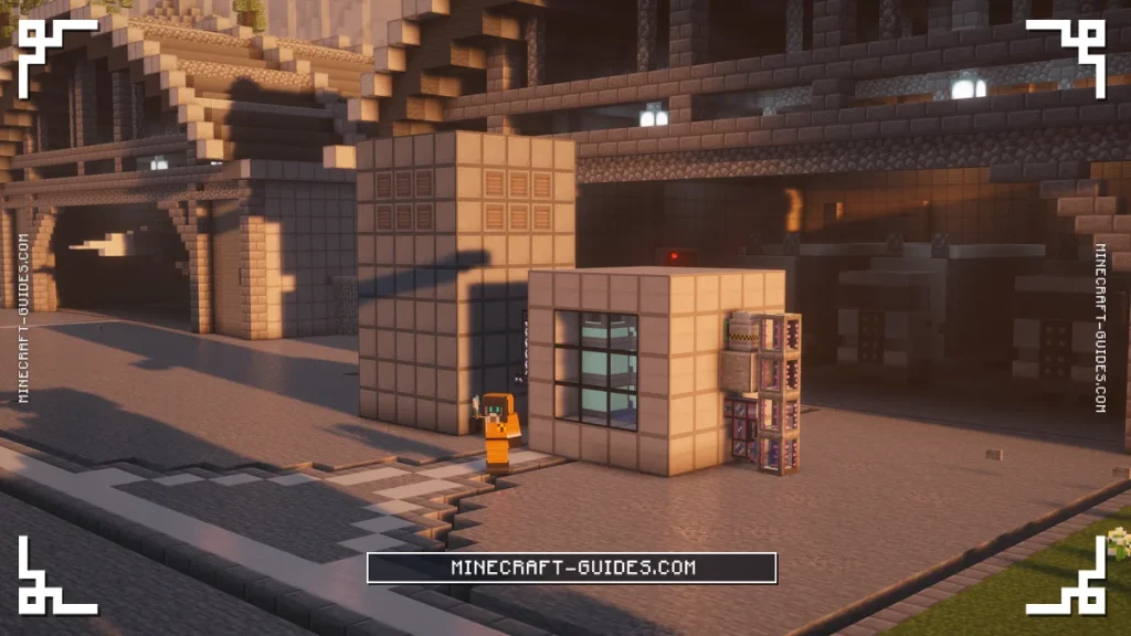
How much energy you’ll get from each mB of Steam is set by the blades, and how much Steam can pass through each tick is set by the vents. So a tall turbine with few vents is efficient but slow, whereas a short wide one moves a lot of Steam for less power from each mB.
Blades and coils
Each Turbine Blade adds about 0.14 FE (0.36 J) for every mB of Steam, up to 4 FE per mB with all 28 blades. The blades only count if there are coils to match though, as one  Electromagnetic Coil serves 4 blades.
That means 10 blades need 3 coils and the full 28 need 7, and any coils beyond that do nothing. If you’ve got too few, the statistics tab in the turbine’s screen will mark the coils in red as the limiting part.
Vents and dispersers
Every Turbine Vent lets 32,000 mB of Steam through each tick, and in nearly every build it’s the vents that decide the turbine’s top speed. The Pressure Dispersers have a limit of their own, but it’s only reached in the very smallest turbines.
This is why it’s worth using a vent in every spot that allows one, which is the walls from the complex layer upward and the middle of the roof. The edges and corners still have to be casing, so a 5×5 roof only has room for 9 of them.
It follows the Steam you give it
The turbine doesn’t jump straight to its maximum, as the rate it uses Steam depends on how full its Steam tank is. With a small supply the tank will sit low and the output stays low, and it only reaches the top figure when the tank is full.
It’ll also stop using Steam completely once its energy buffer is full, so the power needs somewhere to go. With a reactor on the other end this matters a lot, and the dumping setting further down is there to deal with it.
Getting the Water back
Used Steam turns back into Water, but only if there are  Saturating Condensers inside, and each one returns up to 64,000 mB a tick. This Water comes out of the vents, not the valves, so the pipe back to the reactor or boiler has to touch a Turbine Vent.
The 5x5x9 turbine only has room for 6 condensers, which will return a little over a third of the Steam at full flow. The rest is lost, so you’ll want an  Electric Pump topping up the Water on the other side as well.
Build Rules
The length and width both have to be odd numbers from 5 to 17, so that there’s a single center block for the rotors, and the height can be anything from 5 to 18. They don’t have to match, so a 5×9 footprint is fine, although the narrower side is what limits the rotors.
| Part | Where it goes |
|---|---|
| Turbine Casing | Every edge and corner |
| Turbine Valve, Structural Glass | Inside a face, never an edge or corner |
| Turbine Rotor | One unbroken center column, from the layer above the floor |
| Rotational Complex | On top of the highest rotor, only one |
| Pressure Disperser | The rest of the complex layer, nowhere else |
| Electromagnetic Coil | Above the complex, every coil touching that group |
| Saturating Condenser | Above the disperser layer, optional |
| Turbine Vent | On a face at the complex layer or higher, at least one |
The inside can only hold turbine parts and air, so a  Torch or some Water left in there will stop it forming. Right-click the casing and the chat message will point at the block that’s in the way.
The width also limits how many rotors the turbine can have, as a narrow one isn’t allowed to be too tall. The height takes up four layers on top of the rotors as well, which are the floor, the complex layer, a layer for the coils and the roof.
| Narrower Side | Most Rotors | Most Blades |
|---|---|---|
| 5 | 5 | 10 |
| 7 | 9 | 18 |
| 9 | 13 | 26 |
| 11 or more | 14 | 28 |
So the full 28 blades need a turbine that’s at least 11 wide and the full 18 tall. A 5 wide turbine can still be built taller than 9, but the extra layers will only give you room for more vents and condensers, not rotors.
Why It Won’t Form
When a turbine doesn’t form, right-clicking its casing will usually print the reason in chat, with the coordinates of the block that’s wrong. It checks the rules in order and stops at the first one that fails, so you might have to fix one thing and click again to see the next.
| Message in Chat | What to Fix |
|---|---|
| Width and length of structure must be odd | One side is an even number of blocks |
| Couldn’t create frame, invalid block | A vent, valve or glass is on an edge or corner, or a wall has another block in it |
| Inner structure contains an illegal block | Something inside isn’t a turbine part |
| No Rotational Complex present | It’s missing |
| Complex must be centered above Turbine Rotors | It’s off center, or there are two |
| Turbine Rotors must be centered below Rotational Complex | A rotor isn’t in the center column |
| Rotors are invalid (non-contiguous) | There’s a gap in the rotor column |
| Structure is too narrow to support turbine size | Too many rotors for the width |
| Coils must be connected to Rotational Complex | No coil directly above the complex, or one is on its own |
| Dispersers must create complete horizontal layer | A hole in the disperser layer, or one that’s outside it |
| Saturating Condenser must be above Pressure Disperser layer | A condenser is too low |
| Found a Turbine Vent below Pressure Disperser layer | A vent is too low |
| No blades are present on the Turbine Rotor | Blades haven’t been added |
If nothing is printed at all, the box itself is the problem, like a missing wall block or a size outside the limits. The most common mistake is a vent or valve on an edge, as it’s easy to run a row of vents all the way to the corner of the roof.
Sizes, Max Size and Output Calculator
These figures are for a turbine with a vent in every spot that allows one and a full Steam tank. The Steam column is what you’ll need to supply for that output, and anything less will give you less power in proportion.
| Size | Rotors and Blades | Coils | Vents | Steam per Tick | Max Output |
|---|---|---|---|---|---|
| 5x5x5 | 1 and 2 | 1 | 33 | 256,000 mB | 73,142 FE/t |
| 5x5x9 | 5 and 10 | 3 | 33 | 1,056,000 mB | 1.51 million FE/t |
| 7x7x9 | 5 and 10 | 3 | 65 | 2,080,000 mB | 2.97 million FE/t |
| 9x9x11 | 6 and 12 | 3 | 133 | 4,256,000 mB | 7.30 million FE/t |
| 9x9x18 | 13 and 26 | 7 | 133 | 4,256,000 mB | 15.81 million FE/t |
| 17x17x18 | 14 and 28 | 7 | 345 | 11,040,000 mB | 44.16 million FE/t |
| 17x17x18 | 10 and 20 | 5 | 585 | 18,720,000 mB | 53.49 million FE/t |
The largest turbine is 17x17x18, and with all 28 blades it makes 44.16 million FE/t. It’s able to go higher with fewer rotors though, as every rotor layer you take out leaves room for 60 more vents, and 10 rotors gives the highest output at 53.49 million FE/t.
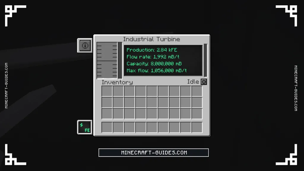
That version needs a lot more Steam for each FE, so it only suits a setup with Steam to spare. When the reactor is the limit, the 28 blade layout is the better one, as it gets the full 4 FE out of every mB.
For any other size, the calculator below will work out the parts and the output from the dimensions you enter. It picks the number of rotors that gives the most power, which can be one fewer than the table has for the same box, as the layer that’s freed up is filled with vents.
Industrial Turbine Calculator
Industrial Turbine sizes with a Turbine Vent in every spot that allows one and a full Steam tank.
| Size | Rotors and Blades | Coils | Vents | Steam per Tick | Max Output |
|---|---|---|---|---|---|
| 5x5x5 | 1 and 2 | 1 | 33 | 256,000 mB | 73,142 FE/t |
| 5x5x9 | 5 and 10 | 3 | 33 | 1,056,000 mB | 1.51 million FE/t |
| 7x7x9 | 5 and 10 | 3 | 65 | 2,080,000 mB | 2.97 million FE/t |
| 9x9x11 | 6 and 12 | 3 | 133 | 4,256,000 mB | 7.3 million FE/t |
| 9x9x18 | 13 and 26 | 7 | 133 | 4,256,000 mB | 15.81 million FE/t |
| 17x17x18 | 14 and 28 | 7 | 345 | 11,040,000 mB | 44.16 million FE/t |
| 17x17x18 | 10 and 20 | 5 | 585 | 18,720,000 mB | 53.49 million FE/t |
Parts: Turbine Casing, Turbine Valve, Turbine Vent, Turbine Rotor, Turbine Blade, Rotational Complex, Pressure Disperser, Electromagnetic Coil, Saturating Condenser.
Matching it to a reactor
A Water cooled Fission Reactor gives 20,000 mB of Steam a tick for every 1 mB a tick of burn rate. So the 5x5x9 turbine is able to take the Steam from a burn rate of about 52, and it’ll make around 28,500 FE/t for each 1 mB of that burn rate.
A turbine with all 28 blades gets 80,000 FE/t from the same 1 mB of burn rate instead, which is why height is worth building for. It’s fine to run more than one turbine from a reactor as well, as long as each of them has its own Water return.
Upgrades and Automation
The turbine doesn’t take any upgrades, so the size and the parts inside are the only things that change its output. Its screen has a button for what to do with Steam it can’t use, and this has three settings.
| Setting | What It Does |
|---|---|
| Idle | Keeps all of the Steam, which is the default |
| Dumping Excess | Vents Steam only while the tank is more than 85% full |
| Dumping | Vents Steam all the time |
Dumped Steam is destroyed and gives no Water back, so it’s a safety setting and not something to leave on Dumping. With a reactor attached, Dumping Excess is the one to use, as the turbine will keep taking Steam even when its energy buffer has filled up.
A turbine left on Idle with a full energy buffer stops taking Steam, and by our reading of the code the reactor will then throw its own Steam away and slowly lose the Water from its loop. Keeping the power drawn down, or switching to the Dumping Excess setting, should prevent it.
A Comparator against a Turbine Valve reads how full the Steam tank is, which can be used to slow a reactor down before the tank fills. For the power side, an Induction Matrix is the usual thing to put on the valve, as the turbine makes far more than an Energy Cube is able to hold.
The turbine is only half of the setup, as it still needs something making the Steam. That’s usually the Fission Reactor, which is the next thing to build once the turbine has formed.
FAQ
Build a hollow box of Turbine Casing with odd sides from 5 to 17 and a height from 5 to 18. Put a column of Turbine Rotors up the center from the floor, a Rotational Complex on top, Pressure Dispersers around the complex, and Electromagnetic Coils above it. Then add Turbine Vents on the upper walls and roof, a Turbine Valve lower down, and 2 Turbine Blades on each rotor.
Right-click the casing and it’ll print the first rule that’s failing in chat. The usual causes are an even side length, a vent or valve on an edge or corner, a gap in the disperser layer, a coil that isn’t touching the one above the complex, or blades that haven’t been added to the rotors yet.
The largest is 17x17x18, which holds 14 rotors and 28 blades and makes 44.16 million FE/t from about 11 million mB of Steam a tick. Dropping to 10 rotors makes room for more vents and raises it to 53.49 million FE/t, although it’ll use a lot more Steam to get there.
Each rotor holds 2 Turbine Blades and one Electromagnetic Coil serves 4 blades, so divide the blades by four and round up. A 5 rotor turbine with 10 blades needs 3 coils, whereas the full 28 blades need 7, and extra coils won’t add anything.


